Alternator Circuit Explained : Alternator Automotive Wikipedia : All cars with an internal combustion engine except for some hybrids have an alternator.. Part of that circuit is another set of diodes mounted inside the alternator called the diode trio. Alternators produce alternating current through a process known as electromagnetism. Disconnect the wiring from the existing alternator. Alternator internal circuit to understand the… Check the wires for the alternator and the circuit.
Alternators that have one positive wire connected to the alternator has the ground connected to its case. A basic alternator is made up of a series of alternating finger pole pieces placed around coil wires called field windings that wrap around an iron core on the rotor shaft. Wiring diagram how an alternator works. Wiring diagram also offers helpful recommendations for tasks that may require some additional equipment. The diode trio takes current coming from the three stator windings and passes a small amount through three diodes so that only the positive.
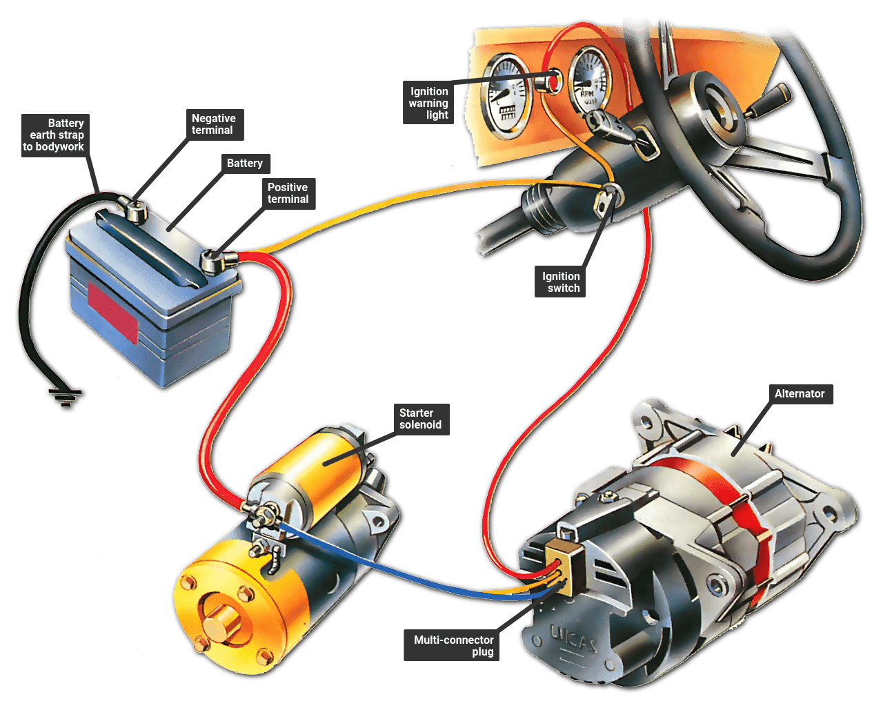
Billavista Com Alternator Bible Tech Article By Billavista from www.billavista.com P0562 (charging system low voltage). Once the engine is in the idling mode the dynamo starts getting a field current through the ignition warning lamp. A key to identifying your alternator terminals posted by peter kennedy on 12/13/2018 to alternators this key might be helpful to identify the terminals on your alternators, as you can see the same function can have different designations depending on the make and model of alternator P16bc (alternator fr terminal circuit/igp circuit low voltage) will be set. Four wires connect the alternator to the rest of the charging system. Pin on golf cart battery vehicle. Alternators are mounted to the engine and are operated by a serpentine belt or powered by the crankshaft directly. The alternator has a rotor that spins when the engine cranks.
Part of that circuit is another set of diodes mounted inside the alternator called the diode trio.
The only true way to monitor the alternator output is to observe the output voltage and current waveforms using an oscilloscope. An alternator is an electrical generator that converts mechanical energy to electrical energy in the form of alternating current. In this article, the design of the alternator circuit will be explained in detail, with some. The easiest way to test it is by using a voltmeter. Alternator internal circuit to understand the… 12 volt alternator installation operation manual introduction thank you for choosing a balmarr high output alternator. Wiring diagram also offers helpful recommendations for tasks that may require some additional equipment. Here we have provided a schematic diagram of brushless alternator. The alternator has a rotor that spins when the engine cranks. Part of that circuit is another set of diodes mounted inside the alternator called the diode trio. The headlights, dashboard lights, radio and interior lights all rely on the alternator to keep the battery charged and the car operating. Help us to make future videos for you. The diode trio takes current coming from the three stator windings and passes a small amount through three diodes so that only the positive.
Pin on golf cart battery vehicle. A basic alternator is made up of a series of alternating finger pole pieces placed around coil wires called field windings that wrap around an iron core on the rotor shaft. The voltage regulator senses the alternator output voltage, though the monitoring location varies. The following information is presented as a guide when wiring and troubleshooting alternators. The basic operation is as described below, except the alternator only uses 6 diodes and has an external regulator and energisation circuit.
Alternators Part One from www.flight-mechanic.com The voltages from a power supply are held within a limit that is consistent with the other electrical components by voltage regulators (vrs). Once you have determined that the new alternator is the correct replacement for your existing model: The stator is fixed to the shell of the alternator, and does not turn. The regulator switches the rotor control circuit on and off,. Alternator circuit explained / diagram skytronics jasco alternator 24 volt wiring diagram full version hd quality wiring diagram / armature resistance /phase of the alternator, open circuit and short circuit characteristics of the alternator. Short circuit ratio is the ratio of field current. Typical alternator, or related, faults are: A basic alternator is made up of a series of alternating finger pole pieces placed around coil wires called field windings that wrap around an iron core on the rotor shaft.
Short or open circuits, or high resistances, in the stator windings.
Pin on golf cart battery vehicle. Wiring diagram how an alternator works. Today, i will be sharing some basic info about the terminal connections of an alternator with full explanation about its working of it field (rot. As the rotor turns within the stator windings, the magnetic field of the rotor sweeps through the stator windings, producing an electrical current in the windings. Honda alternator and charging systems explained. Disconnect the batteries and/or turn the switch to the off setting. Part of that circuit is another set of diodes mounted inside the alternator called the diode trio. First, we will discuss how an alternator works. Once the engine is in the idling mode the dynamo starts getting a field current through the ignition warning lamp. Typical alternator, or related, faults are: The headlights, dashboard lights, radio and interior lights all rely on the alternator to keep the battery charged and the car operating. The following information is presented as a guide when wiring and troubleshooting alternators. The voltages from a power supply are held within a limit that is consistent with the other electrical components by voltage regulators (vrs).
How to test an alternator. A basic alternator is made up of a series of alternating finger pole pieces placed around coil wires called field windings that wrap around an iron core on the rotor shaft. An alternator is a generator of electric power in a car and is a major component of the vehicle's charging system. There is another circuit in the alternator to control the charging system warning lamp that is on the dash. An alternator is an electrical generator that converts mechanical energy to electrical energy in the form of alternating current.
Troubleshooting The Ignition Warning Light How A Car Works from www.howacarworks.com Wiring diagram also offers helpful recommendations for tasks that may require some additional equipment. Disconnect the batteries and/or turn the switch to the off setting. 12 volt alternator installation operation manual introduction thank you for choosing a balmarr high output alternator. Pin on golf cart battery vehicle. Alternators that have one positive wire connected to the alternator has the ground connected to its case. Honda alternator and charging systems explained. Because of the rotation of the rotor, an alternating current is produced. The alternator has a rotor that spins when the engine cranks.
P0562 (charging system low voltage).
Continuing with the topic of alternators the post here is on internal circuit and output voltage regulation. Poor battery states of health or charge. Alternators that have one positive wire connected to the alternator has the ground connected to its case. Once the vehicle is running, pulleys on the running engine rotate a belt connected to the alternator, which then causes the internal coils of the device to generate power to replenish the battery for the next start and provide ongoing electricity to operate the vehicle's accessories and lights while in operation. Alternator circuit explained / diagram skytronics jasco alternator 24 volt wiring diagram full version hd quality wiring diagram / armature resistance /phase of the alternator, open circuit and short circuit characteristics of the alternator. Four wires connect the alternator to the rest of the charging system. P0562 (charging system low voltage). Günstig im online shop kaufen! The only true way to monitor the alternator output is to observe the output voltage and current waveforms using an oscilloscope. Short circuit ratio is the ratio of field current. Because of the rotation of the rotor, an alternating current is produced. Units, the benefits of fitting a modern alternator with its much simpler circuit after a failure, will outweigh the cost. As the rotor turns within the stator windings, the magnetic field of the rotor sweeps through the stator windings, producing an electrical current in the windings.